BIOS Verb-Table
在 BIOS 中,經常要對 HDMI Codec 填寫 Verb-Table,Verb 其實指的是對 Codec 下的命令,而 Verb-Table 指的是對 Codec 下的一連串命令 (通常是寫入到 Configuration Default Register)。這些命令通常是因為每一個主機板的 Pin Widget 設計上的不同,也造成了 Verb-Table 必須填寫不同的內容。
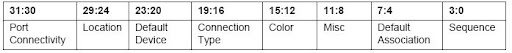
例如: Pin Widget 的 Configuration Default Register 為 0x01014110 代表著
Port Connectivity: The Port Complex is connected to a jack
Location: External on Primary Chassis, Rear
Default Device: Line Out
Connection Type: 1/8" stereo/mono
Color: Green
Misc: Jack detect override
Default Association: Group 1
Sequence: Sequence 0
Port Connectivity: The Port Complex is connected to a jack
Location: External on Primary Chassis, Rear
Default Device: Line Out
Connection Type: 1/8" stereo/mono
Color: Green
Misc: Jack detect override
Default Association: Group 1
Sequence: Sequence 0
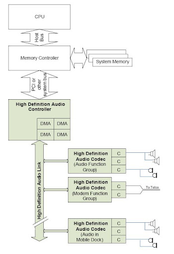
Codec: 一個 HD Audio Link 可以連接多個 Codec, 而 Codec 又可以連接多個 Converter (下圖中的 C)。Converter 負責轉換 Analog signal 與 Digital stream,同類型的 Converter 會連接至同一個 Codec。而所有的 Codec 都會透過 HD Audio Link 來和 HD Audio Controller 溝通。
下圖為 HD Audio 的架構 (圖片來源: HD Audio Spec 1.0)
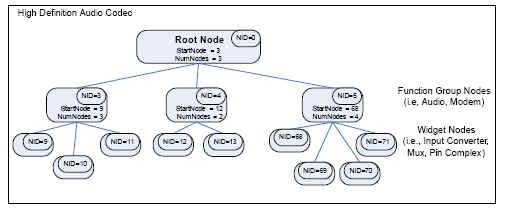
HDMI Codec 的架構為一個 Tree,其最上層為 Root Node,而其下又分成各種不同的 Function Group,在 Function Group 之下又各自有不同的 Widget。
Function Group: 特定應用模組的集合,例如 Audio Function Group, Modem Function Group 等等
Widget: 為 Function Group 中的特定應用模組,例如 Pin Widget, Mixer Widget, Power Widget
Node: 在 Tree 中的每個節點稱之為 Node,例如 Root Node, Function Group Node, Widget Node。
NID: 每一個 Node 有一個唯一的 ID,稱之為 NID (Node ID),其中 Root Node 的 ID 為 0。
Verb: 向 Codec 下的命令稱之為 Verb
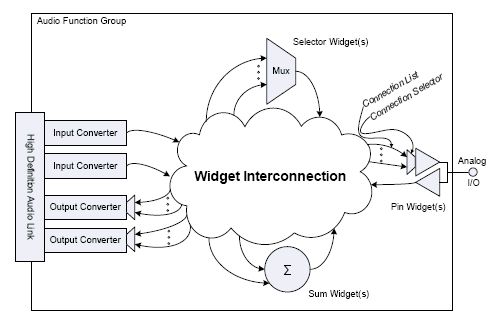
下圖為 Codec 的架構 (圖片來源: HD Audio Spec 1.0)
下圖為樹狀架構的圖例 (圖片來源: HD Audio Spec 1.0)
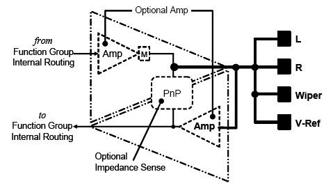
Pin Widget 主要為聲音提供外部數位或類比的連接。Pin Widget 主要可以設定下列的參數:
1. Input, Output or Both
2. Stereo or mono (1- or 2- channel)
3. Plug (Presence) detection
4. Attached device impedance sensing
5. VRef bias for microphone support
(有關 Pin Widget 的詳細資訊可參考 7.2.3.3 Pin Widget 的內容)
下圖為 Pin Widget (圖片來源: HD Audio Spec 1.0)
每個 Pin Widget 都必須包含一個 Configuration Default Register,其內容定義如下
(完整的 Configuration Default Register 可以參考 7.3.3.31 Configuration Default 的內容)
Port Connectivity[1:0]
indicates the external connectivity of the Pin Complex. Software can use this value to know what Pin Complexes are connected to jacks, internal devices, or not connected at all.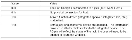
Location[5:0]
indicates the physical location of the jack or device to which the pin complex is connected. This allows software to indicate, for instance, that the device is the “Front Panel Headphone Jack” as opposed to rear panel connections. 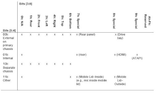
Default Device[3:0]
indicates the intended use of the jack or device. This can indicate either the label on the jack or the device that is hardwired to the port, as with integrated speakers and the like.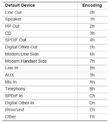
Connection Type[3:0]
indicates the type of physical connection, such as a 1/8-inch stereo jack or an optical digital connector, etc. Software can use this information to provide helpful user interface descriptions to the user or to modify reported codec capabilities based on the capabilities of the physical transport external to the codec.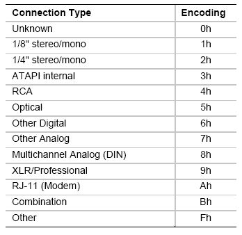
Color[3:0]
indicates the color of the physical jack for use by software.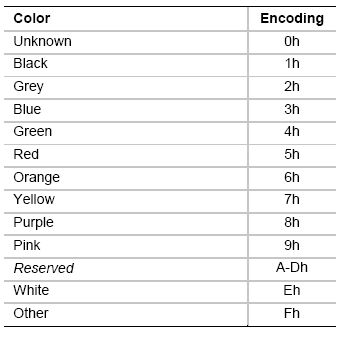
Misc[3:0]
is a bit field used to indicate other information about the jack. Currently, only bit 0 is defined. If bit 0 is set, it indicates that the jack has no presence detect capability, so even if a Pin Complex indicates that the codec hardware supports the presence detect functionality on the jack, the external circuitry is not capable of supporting the functionality.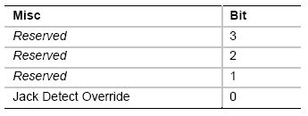
資料來源: http://www.wretch.cc/blog/hyper0672/9928582
沒有留言:
張貼留言